If unable to push commits, use git clone ssh://USERNAME@git.code.sf.net/u/USERNAME/PROJECTNAME instead of proposed git clone ssh://USERNAME@git.code.sf.net/u/USERNAME/PROJECTNAME u-USERNAME-PROJECTNAME
Archive for category Hobbies
LCM-WM002
Jul 24
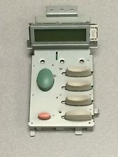
LCM-WM002 is a 16×2 LCD display, coming from a “refurbished” equipment. To be true, the equipment was a HP 5000 / 5100 laser printer, and the LCD has a bezel and a PCB with buttons attached, named ESU19516, part number RG5-5438. Read the rest of this entry »
Rant on Apache2
Jul 23
Recently I was trying to move my sites to SSL – for various reasons.
The test site went fluently, while the work machine refused to serve SSL content. While testing with ‘wget’, the error I received was
GnuTLS: An unexpected TLS packet was received.Rant on AVR ISRs
Mar 1
Once you define an ISR bit in the TIMSKx, the appropriate ISR must be attached.
Lost almost a day on non functioning serial port, until stumbled upon the post in stackoverflow.com
So, when copypasting
TIMSK1 |= (1 << TOIE1) | (1 << OCIE1A);
be sure to define both
ISR(TIMER1_OVF_vect) {

...

}
and
ISR (TIMER1_COMPA_vect)

{

...

}
Ever played with ArduinoSerialCommand? Nice library, but it lacks the possibility to retrieve current command. This possibility is waiting in the pull request for a long time, so if you deadly need it – merge it by yourself.
Meet the fMRI Parrot
Nov 6
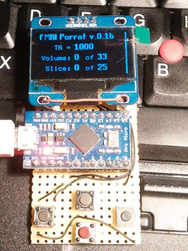
What the heck is “fMRI Parrot”?
First of all, the heck is fMRI. fMRI stands for “Functional Magnetic Resonace Imaging”, as defined in Wikipedia. It involves tons of expensive hardware, like Magnetic Resonance machine, and software, used to reconstruct the scanned volumes. During fMRI scanning a series of stimulus are applied to the patient and the brain is scanned using fast scanning MRI techniques. The aim of fMRI is to record immediate changes happening in particular areas of the brain.
The single MRI scan is called “volume”. It is created from a series of slices of the predefined thickness. Having more slices creates more detailed volume and extends acquisition time. As the changes of the brain activity are momentary, a short volume acquisition interval, named TR or “Time Repetition” is needed. Usually it varies from 7 to 1.5 seconds, depending on the capabilities of the MR machine. Short TR time supposes lower quality scans, compared to the “traditional” MR scanning. So the level of detail of particular volume is a trade off between time and specific requirements.
The fMRI scans consists from a number of volumes, recorded at particular intervals. The key condition for a successful scan is the precise timing. In order to find a region with elevated activity, a stimulus must be started just when the volume acquisition begins. For this the MRI machine may expose a short pulse – start of a volume. The pulse may be brought to the MRI control room via the interface box and the required stimulus started automatically. Some stimulus require the patient to respond, eg. press the predefined button. The response from the patient is also brought to the MRI control room. As there are special requirements for any hardware at the MRI machine, only certified equipment is allowed to the MR room. The requirement at the MRI control room are more relaxed as well as the choice of the equipment There are different vendors of the interface boxes and response buttons, NordicNeuroLab (NNL) being one of them.
In order to create the simulation series, or paradigmas in fMRI terminology, a lot of time is needed. Each paradigma is to be verified before the clinical test, while some of them can not be tested without a signal form the MRI scanner or a response from the patient. There is no need to say the MRI equipment is expensive, so is the time spent in the MRI machine. Most of the MRI scanner interface boxed can be used in so called “simulation” mode, sending particular responses at the predefined moments, without actually running the scanner. For example the Sync Box from NordicNeuroLab will send “S” symbol at the start of the volume acquisition, while fORP from Cambridge Reserch Systems is to send “5”. So what is actually required to test a paradigma, is the response from the scan… WAIT!
It’s must not be the MRI scanner nor the interface box.
The things: short story
Aug 1
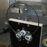
A bending jig, a piece of stainless steel
 Read the rest of this entry »
Hacking A6628SEDT
Dec 8
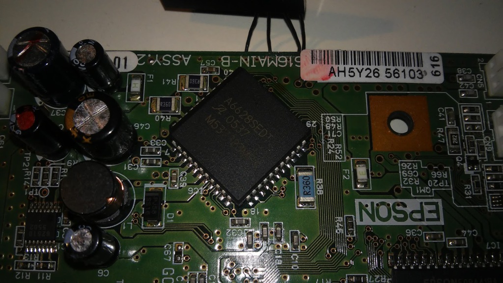
The A6628SEDT is a PLCC 44 packed dual motor driver, running in my old Epson printer.
The idea is to controll the chip by some Arduino and make it print PCBs, like these guys did.
The datasheet for the chip is absent, but thes is connection diagram on the printer’s Service Manual.
It seems the chip is dual version of some Allegro motor controllers, having two indpendent data channels and dual H-bridges (or kind of).
According to the schemacics, paper feeder is controled via data channel 0 on pins 28, 29 and 30 (CLK, Data, Strobe accordingly). The carriage motor is controlled via data channel 1 on pins 40 (CLK), 38 (Data) and 39 (Strobe). Read the rest of this entry »
PCB experiments with the UV
Apr 15
The PCB:
A scrap piece of 5+ year old UV sensitive PCB. The sticky black residue on the PCB is the clue from the protective foil.
The mask:
Transparent foil for laser printers. Printed on Samsung CLP-320 in greyscale mode. Single layer.
The traces:
- 0,1 mm with the gap of 0,1 mm
- 0,1 mm with the gap of 0,2 mm
- 0,2 mm with the gap of 0,2 mm
- 0,2 mm with the gap of 0,3 mm
- 0,2 mm with the gap of 0,4 mm
- 0,3 mm with the gap of 0,2 mm
- 0,3 mm with the gap of 0,3 mm
- 0,2 mm with the gap of 0,6 mm
The rest of the PCB will be used for the rectifier circuit. Read the rest of this entry »
I was working on semi – automated solution to enter door handiness in Revit models. The existing solutions are either quite expensive (like Reforma Swing Direction) or has weird assumptions.
My intial setup is Dynamo and the Dynamo Door Set Handing module from http://archi-lab.net/. It has fine tutorials, so you only need to create your model in Dynamo.
The weird thing on door handines is it is different in some countries.
- Door handiness in Germany is defined as hinge position on the door, when one is pulling the door to open. if the hinges are on the left side, the door is left-handed, and if the hinges are on the right side, the door is right-handed. I will refer it ad “DIN – style”.
- The IFC, together with ISO 16739 defines door handiness as the position of “positive Y axis”, which is definitelly the position of door handle when puling. I will refer it as “ISO – style”.
- Americans use ISO style, but also has “reversed” option. I still have no idea on this option, as “reversed right” is “left”.
So, what’s to do?