We have a computer room in our local university, ind it’s quite bussy. The main problem it became (this is another story) too long to be usable and there was a strong demand for the screencast view right on the student’s workplace. Yes we do use beamers, but the view was too small to dead the text on the screen.
And so the project was born. There is single seat where the view originates and multiple locations where it should be visible. The system must be easily expandable and upgradeable, no vendor lock-ins. All the points in the systems should be easily adjustable and replaceable.
HDMI was chosen as stream distribution transport, having slight advantages over DisplayPort in our situation. To switch the video sources a 4-to-1 HDMI switch was used. Every source signal is converted to HMDI using appropriate media converters and is fed to the distribution network. A combined bus – start topology is used for distribution, where the bus is continued from one of the outputs of a HDMI splitter, thus providing signal reconditioning to the next bus segment. To reach the “isolated island”, the HDMI over Cat-5 converters are used, so no extra cabling and a lot of work to install it was involved.
Dell U2412 LCD monitors are used as endpoints, just because we had a lot of them lying around. A single screen is shared for the two workspaces. As the monitor provides either DisplayPort or DVI-D digital inputs, a passive converter was used to supply HDMI signal to DVI-D input. Need to note bus signaling is the same for HDMI and DVI-D, the difference is the form factor and pin numbers.
The system has 4 HDMI inputs, wired either directly or via media converters. Right now it is possible to connect the classroom’s PC via HDMI (using DisplayPort to HDMI cambe), laptop via HDMI or VGA cables. The last input is unused and reserved for the future.
Total performance of the system is quite good. It can accept Full HD (1920×1080 px) signal. The view latency is almost invisible comparing the LCDs on the longest part of the network side by side, although it has quite long delays in the initial signal propagation while changing video sources.
The HDMI switch has physical pushbutton and remote control capability via infrared (IR) remote, but not via network or external panel. The problem the IR remote is in the single instance and it is prominent to be lost. What if i make a second remote?
And so the second project was born. It uses Arduino to command the HDMI switch via IR channel, the LCD screen to indicate current video source and pushbutton to cycle them. The firmware, called ‘HDMI-swither’ is quite simple, yet has enough capabilities: I can name video sources and disable or enable them without recompiling the firmware; the principal settings are stored in the flash and are almost immune to power losses. You can find it in the Github.
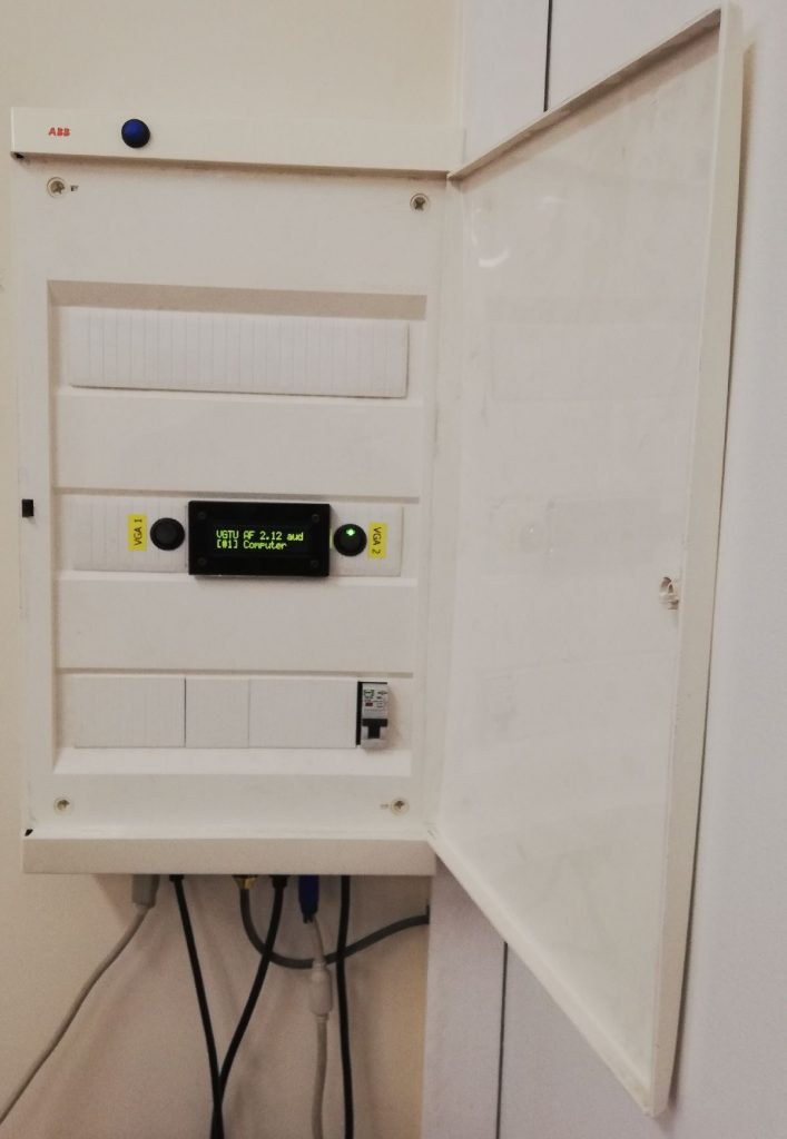
Blue button will cycle the inputs, amber colour LCD will indicate it. The case has external doors to minimize unnecessary light.
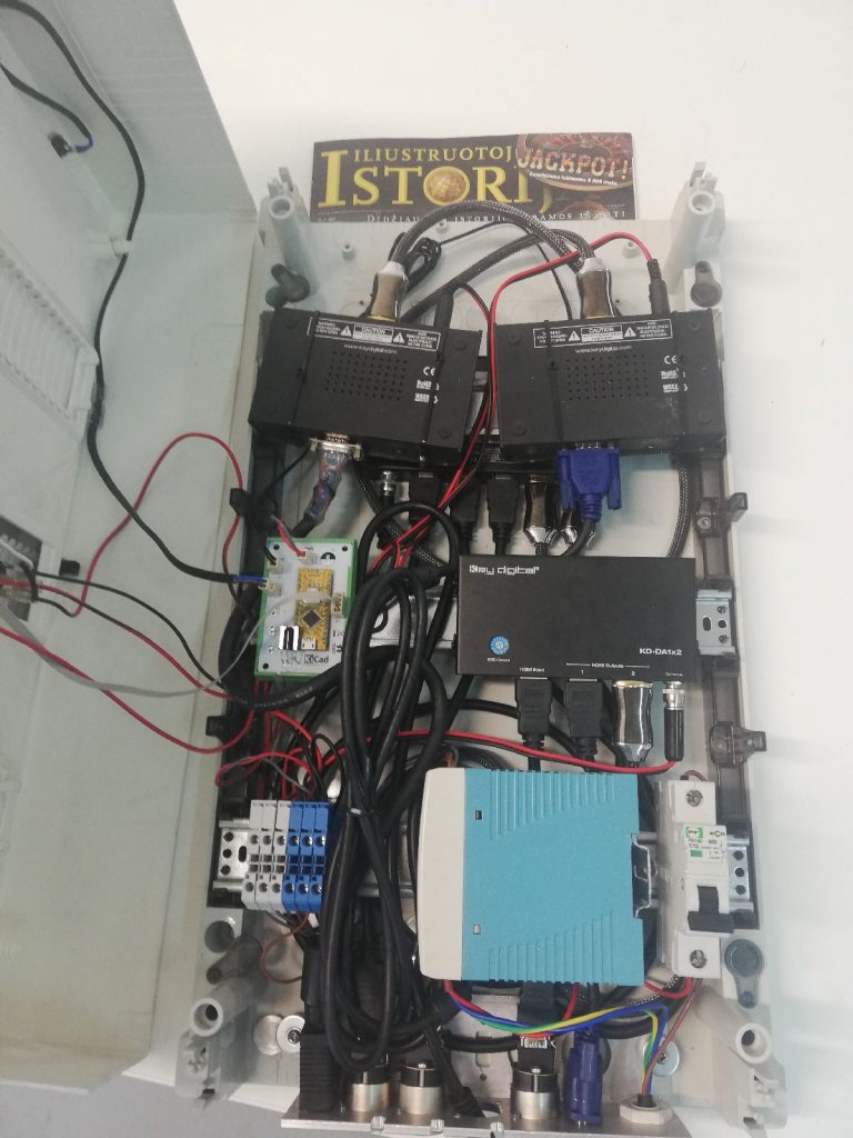
Almost no hot glue was used. Zip ties had to be replaced with 3D printed brackets. Brackets failed, while zip ties obviously not.
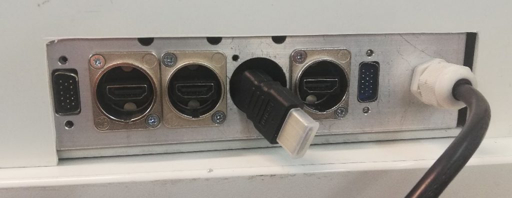
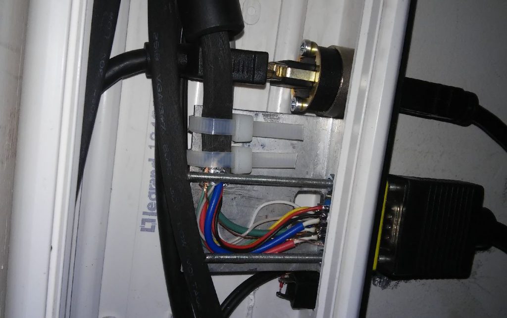
Aluminum corner was used for the bracket. The holes milled with CNC machine. The HDMI-to-HDMI sockets are from Neutrik. VGA cable ends are inserted into the holes, where the gender change adapter will be bolted.
Althow any connector will introduce uncertainty to the system, this is intentional. I keep replacing pigtail cables almost every year, and having to replace a lot of pigtails becomes quite expensive. Before introducing pigtails, i had to replace the entire cable, sometimes reaching 15 meters as it was broken at the connector after intensive and careless use.